
High Quality Spiral Staircase and Spiral Stair Manufacturer
Stairways Inc. is a family-owned and operated spiral stairs and spiral staircases company with three generations of experience in the design, manufacture, production, delivery and installation of a wide range of Spiral Staircases, Spiral Staircase Kits, wood spiral staircases and metal spiral staircases, both in kit form and fully assembled. The national shipping service from your Houston, Texas headquarters expands your reach, making your products accessible to customers across the country. This is particularly beneficial for those who may not have local options for high-quality spiral staircases. We manufacture and design spiral stairs for unique industrial, commercial and residential applications. The fact that it's a family-owned and operated business with three generations of expertise adds a personal touch to your services. With over 40 years of experience, our team of experts works with you to create a spiral staircase to your exact specifications and needs.
Stairways Inc. can deliver metal spiral staircases, custom circular stairs and staircases, and wood spiral stairs and staircases fully assembled to a client, or in unassembled kit Spiral stair form. Fully assembled metal spiral staircases are fully assembled and welded; while an advantage to delivering a complete metal staircase is that you, the client, will be receiving the highest quality finished spiral stair product, a disadvantage is the freight cost associated with a large (heavy) finished metal spiral staircase. For this reason, Stairways Inc. is proud to offer standard metal spiral staircase and wood spiral staircase kits, which are both relatively inexpensive to purchase and ship (compared to assembled metal stairs and wood stairs).
The advantages of delivering fully assembled metal spiral staircases, such as receiving a high-quality finished product, are balanced with the acknowledgment of potential disadvantages like increased freight costs due to the size and weight of the finished stairs. By transparently addressing these considerations, Stairways Inc. enables clients to make informed decisions based on their specific needs and constraints. The availability of standard metal spiral staircase and wood spiral staircase kits offers a cost-effective alternative. This is particularly beneficial for clients looking to manage both the initial purchase cost and shipping expenses. Kits not only provide affordability but also give clients the option to assemble the staircase themselves, which can be appealing for those who enjoy DIY projects or wish to save on installation costs.
Contact us today to learn more about how we can help build the perfect spiral stairs for your needs and applications! High Quality Spiral Staircase and Spiral Stair Manufacturer. Read More
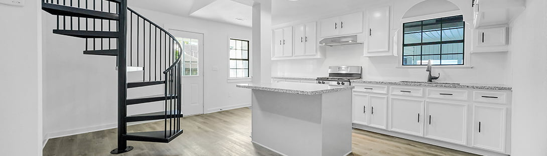
let us design your perfect staircase
With hundreds of options for residential, industrial or commercial spiral stairs, making your perfect spiral staircase is what we do. Browse through our Design Center for design inspiration or pick out the staircase you've always wanted. Then get a custom quote to get started today!

Featured:
In partnership with ARCAT, our commitment to excellence has led us to be industry-leading Building Information Modeling (BIM) models, for spiral stairs.
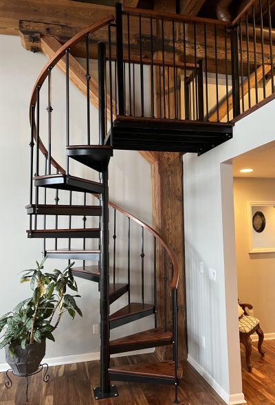
Residential Spiral Stairs
With a variety of options from which to choose, Stairways can make the perfect spiral stairway solution for your home.

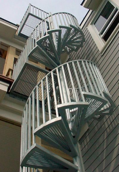
Industrial Spiral Stairs
You need a superior solution to hold up to outdoor conditions. Let Stairways design a quality spiral stair to meet your needs.
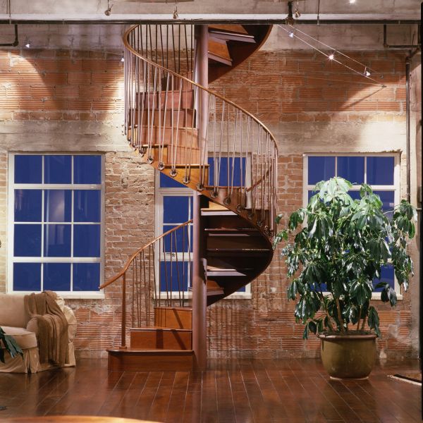
Commercial Spiral Stairs
Explore the functionality and style of our commercial stairs, providing an ideal solution for your space while meeting all building codes. From grand staircases to space-efficient options, our meticulously crafted stairs ensure both safety and aesthetic appeal. Elevate your commercial environment with our premium stairs, where practicality and precision converge seamlessly.

Spiral Stairs professional services
Discover a curated collection of tools and resources for architects, builders, and contractors to ensure your stair project meets exact specifications and building codes. From specialized design software to comprehensive guides, our platform provides essential resources for a seamless and code-compliant stair installation. Craft your stairs to perfection with confidence. We have been helping industry partners provide their clients with custom staircases for over 45 years.
Let Us Build The Perfect Staircase for You
Over 40 Years of Experience
Family Owned and Operated
Customized to Your Specifications
Larger Variety of Materials and Options
Fully Assembled or Easy to Install Kits
Shipped Anywhere in the United States
YOU WILL LOVE OUR SPIRAL OF EXCELLENCE
Our sales rep, Bob O., took great care with our order. It fits perfectly in our small home space, like a well-designed spiral staircase. The exceptional steel quality adds durability. We're impressed with the entire process from start to finish, much like ascending a spiral staircase.
Wendy Heintschel
We recently acquired a set of exquisite spiral stairs from them, seamlessly installing the spiral staircase in our warehouse. Dealing with Mason Anderson was a delight – great product, swift turnaround time, clear communication, and an unbeatable price for our new spiral stairs. I wholeheartedly recommend their exceptional spiral stairs and eagerly anticipate using their services again.
Fit Shop
Mark Anderson's meticulous craftsmanship shines in the creation of our unique spiral stairs. Even from afar in Arkansas, he FaceTimed to ensure the perfection of our spiral stairs. The Stairways team's expert assistance in packing and loading during pickup adds to the seamless experience with these exquisite spiral stairs. Kudos to Mark Anderson and the Stairways team for their dedication to exceptional spiral stairs. Thanks, Walt Taylor.